The diagram below shows a circuit with four gates, where the output from two AND gates are sent into a third AND gate, and the output from that gate is sent into a NOT gate. The circuit has four inputs (A, B, C, D).
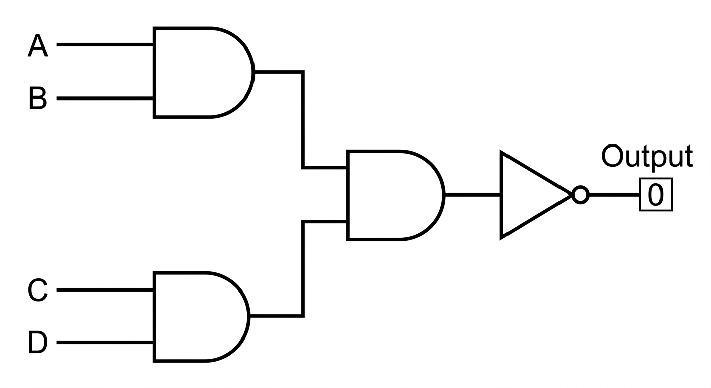
If the final output is 0, what are the possible states of inputs A, B, C, and D?
Identify the target output (e.g., 0 at the end).
Invert the gate logic at each step (e.g., if a NOT gate outputs 0, its input must be 1).
Find required inputs for each previous gate to achieve those signals (e.g., an AND gate needs all 1 to output 1).
Trace back to the primary inputs to determine their necessary states.
