
Clock Tree Structures
Why Do We Need a Buffered Clock Tree?
A simple approach to clock distribution would be to route an individual clock net directly from the clock source to every sequential element and balance the RC delay of each path.
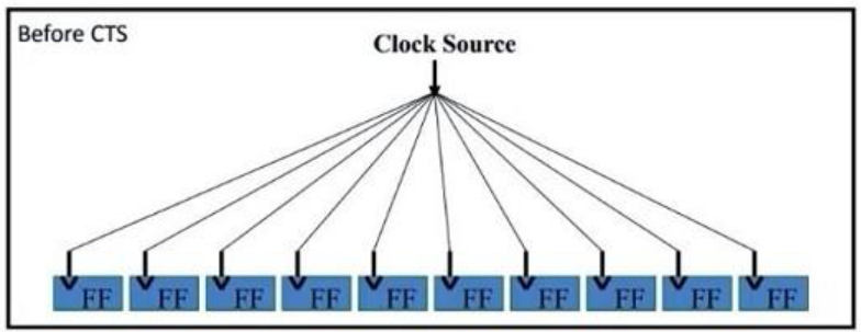
However, this approach has some limitations:
Long clock wires result in higher resistance and capacitance (RC), increasing delay.
Higher capacitance increases dynamic power consumption.
Long interconnects can cause signal integrity issues and poor clock transitions.
To overcome these limitations, a buffered clock tree is used.
In a buffered clock tree, clock buffers are inserted at different levels to divide the clock distribution network into shorter interconnect segments.
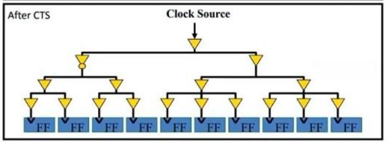
This provides several benefits:
Reduced RC Delay: Shorter interconnect segments help reduce the resistance and capacitance of individual wire segments.
Improved Clock Transition: Buffers restore the clock signal and help maintain acceptable transition times.
Controlled Insertion Delay: A properly designed buffered network helps control the overall clock insertion delay.
Optimized Power Consumption: An optimized distribution network helps control unnecessary switching capacitance and clock power.
Different Clock Distribution Structures
There are three commonly discussed clock distribution structures:
H-Tree
Clock Grid (Mesh)
Clock Spine
1. H-Tree Structure
An H-Tree is a clock distribution structure in which the clock signal is distributed through a hierarchical network of branches arranged in an H-shaped pattern.
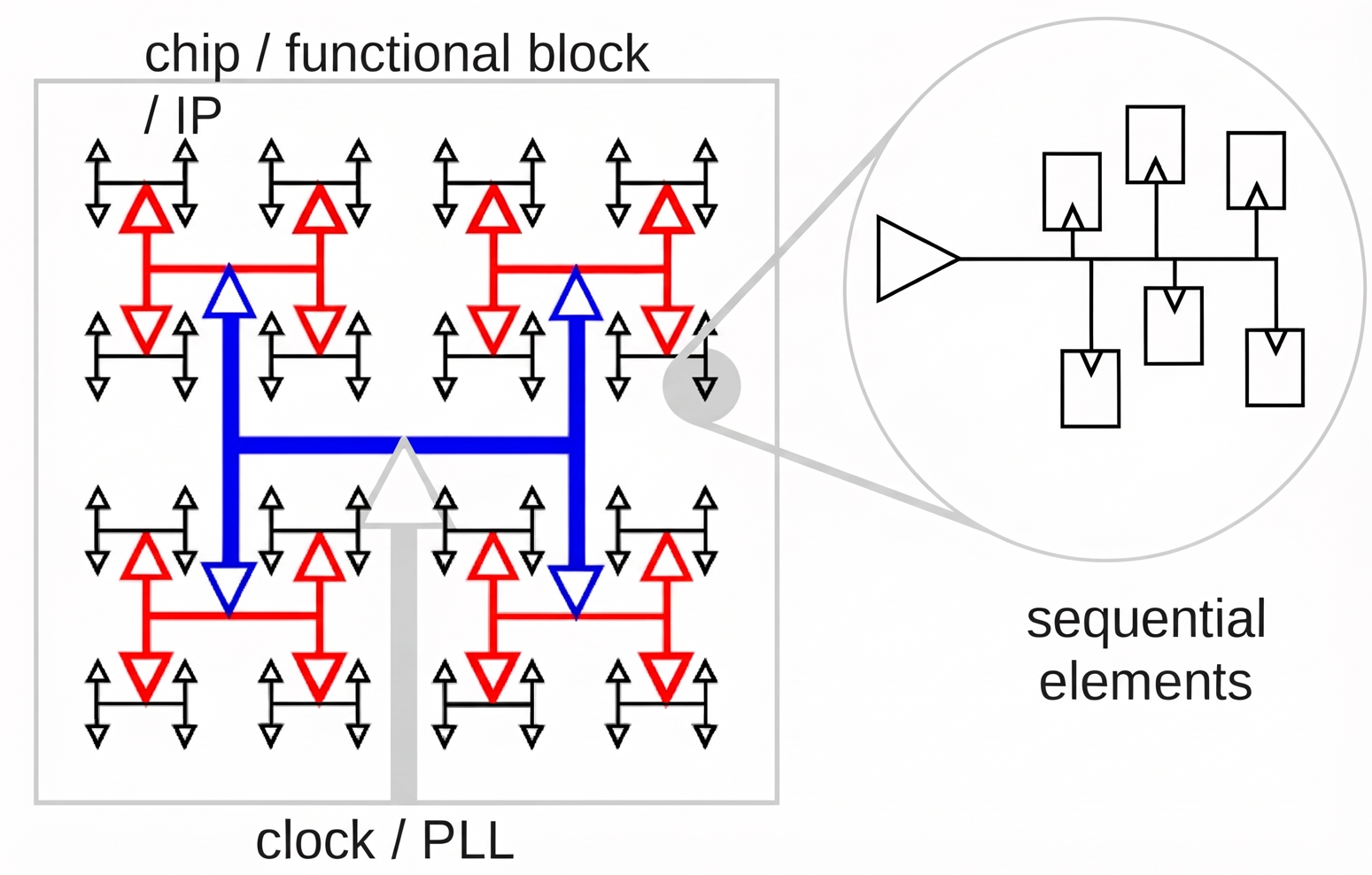
The clock source is placed near the centre of the structure.
The clock signal is divided into multiple branches, with each branch further divided into smaller branches.
The structure is designed to maintain approximately equal path lengths from the clock source to the clock sinks.
Advantages:
Provides low clock skew due to approximately equal path lengths.
Requires relatively fewer routing resources compared to a clock grid.
Provides an efficient clock distribution network.
Disadvantages:
Works best with a relatively regular floorplan.
Difficult to implement when sequential elements are irregularly distributed.
Offers less flexibility when the placement of sequential elements changes.
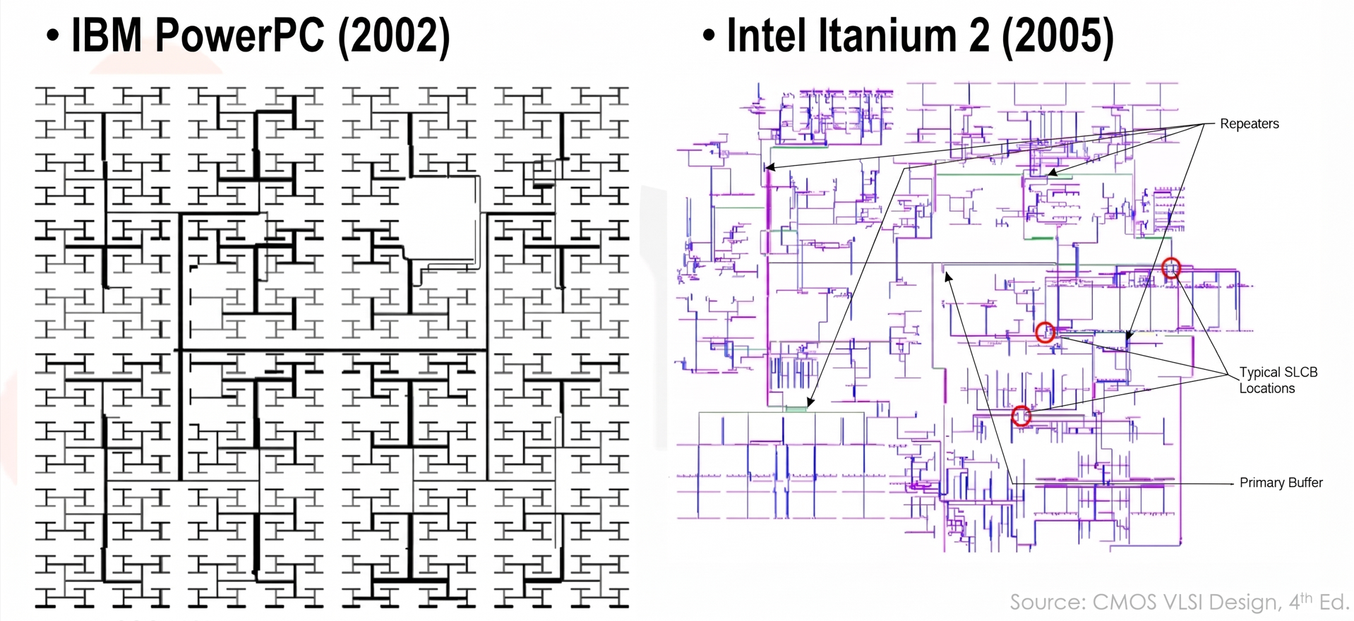
These are few Industrial H-Tree Examples
2. Clock Grid (Mesh) Structure
In a Clock Grid structure, the clock signal is distributed through a network of interconnected horizontal and vertical wires, forming a grid or mesh across the chip.
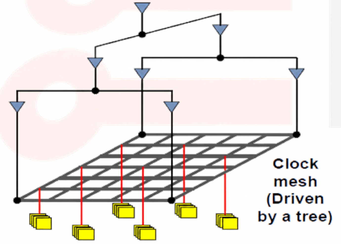
Clock drivers distribute the clock signal to the grid.
The grid provides clock signals at multiple locations across the chip.
Sequential elements receive the clock from nearby grid connections.
Advantages:
Provides very low clock skew.
Less sensitive to variations in the locations and loads of sequential elements.
Offers good tolerance to process variations.
Disadvantages:
Requires a large number of wires and routing resources.
Has high clock capacitance, resulting in increased power consumption.
Requires strong clock drivers to drive the large grid capacitance.
3. Clock Spine Structure
In a Clock Spine structure, one or more wide clock wires, called spines, are used to distribute the clock across the chip. Local clock distribution networks are then connected to these spines to deliver the clock to sequential elements.
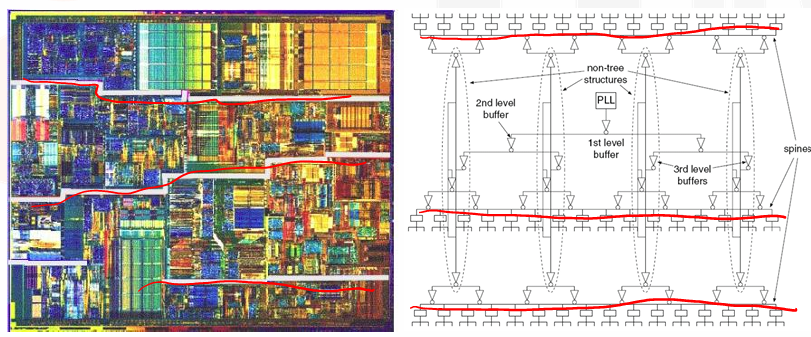
The clock signal is first distributed through the main spine.
Then H-tree is used to distribute the clock from the spine to nearby sequential elements.
The spine provides a low-resistance path for clock distribution.
Advantages:
Provides efficient clock distribution across large regions.
Wide clock wires help reduce resistance and interconnect delay.
Requires fewer routing resources than a full clock grid.
Disadvantages:
Achieving balanced clock arrival times across different regions can be challenging.
Requires careful design of the spine and local clock distribution networks.
Comparison of Clock Distribution Structures
Parameter | H-Tree | Clock Grid | Clock Spine |
|---|---|---|---|
Clock skew | Low | Very low | Depends on balancing |
Routing resources | Low | High | Medium |
Power consumption | Relatively low | High | Medium |
Floorplan flexibility | Low | High | Medium |
Note: These are general comparisons. Actual performance depends on the design, implementation and clock distribution requirements.
Summary
The choice of clock distribution structure depends on the design requirements, floorplan, power budget and acceptable clock skew.
H-Tree: Uses balanced branches to distribute the clock with approximately equal path lengths.
Clock Grid: Uses interconnected wires to distribute the clock across the chip, providing very low skew at the cost of higher power and routing resources.
Clock Spine: Uses wide main clock wires with local distribution networks to deliver the clock across different regions.
Note:
These are different clock distribution architectures. In practical ASIC implementation, conventional CTS tools generally construct a buffered clock tree based on the actual locations of sequential elements. The resulting structure need not be a perfect H-Tree, grid or spine.
Also there are few other clock architectures such as X-tree, try to explore them.